Vibration measurements on reciprocating compressors prove to be difficult due to the natural mechanical movement of this type of machinery. However, there are some important parts that should be monitored for changes in vibration behaviour.
Casing vibration (frame vibration)
Casing vibration results from various forces and movements inside the machine and are part of normal running conditions. Due to the pistons being driven back and forth the entire frame with all its components continuously vibrate, move and deform. Moreover, suction and discharge valves create impacts due to opening and closing during every revolution of the crankshaft. Every force during a revolution has its impact and affects the vibration behaviour of the machine. Such forces include gas load forces, inertial load forces, reciprocating and rotating unbalance forces and gas unbalance forces. It’s important to note that even in optimal process conditions, reciprocating compressors vibrate much more than their rotating equivalents.
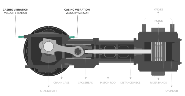
To measure casing vibration on reciprocating compressors, velocity measurements are used. Typically, these are integrating piezoelectric accelerometers or moving coil velocity sensors, as the vibration frequencies for this application usually include components below 10 Hz. The sensors are used to detect defects like unbalance, mechanical looseness and structural or foundation issues. One sensor should be positioned at the drive end side and one at the non-drive end side (figure 1).
Crosshead vibration
The crosshead slides on a lubricated surface and moves back and forth (reciprocating). When the clearance between the crosshead and the surface increases, the crosshead vibration level will also increase. Monitoring crosshead vibration allows the operator to schedule maintenace in time to make sure that the clearance between the surface and the crosshead stays within acceptable limits.
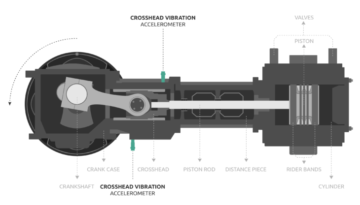
Accelerometers are typically used to measure crosshead vibration due to their ability to monitor high frequency components. These sensors can detect problems related to excessive crosshead clearance, excessive clearance in the crosshead pin bushing and loose or cracked nuts, bolts or pistons. Two sensors should be placed on the crosshead of which the positioning depends on the direction of rotation.
- Clockwise shaft rotation. One accelerometer should be mounted vertically above the crosshead guide on the left, and one vertically below the crosshead guide on the right (figure 2).
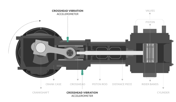
- Counter clockwise shaft rotation. One accelerometer should be mounted vertically below the crosshead guide on the left, and one vertically above the crosshead guide on the right (figure 3).