
A recently overhauled oil pump exhibits an abnormal vibration pattern after a short time in operation. What to do? This report discusses a case in which a deviation is observed during periodic vibration measurements. The issues are characterized by the increase in vibration values, thereby exceeding the limits set by ISO 10816. The installation in question is a steam turbine system, where the main oil pump is driven by a steam turbine. The measurements on this installation are analyzed through Condition Monitoring.
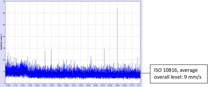
3rd of January
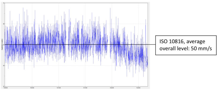
28th of January
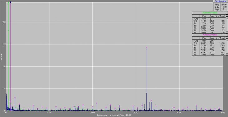
Spectrum of January 28
Analysis
Visible frequencies:
- 1xRPM oil pump (57 Hz) varying between 18 and 30 mm/s RMS.
- 2xRPM oil pump (114 Hz) at 1.5 mm/s.
- 1xRPM turbine (104 Hz) at 2 mm/s.
- Numerous harmonics of the turbine speed, around 1 mm/s per peak.
- The gear mesh frequency of 14 mm/s has sidebands from both speeds (57 Hz and 104 Hz).
Conclusion
The different frequencies with their corresponding levels indicate wear and increased clearances in the gear transmission and bearings. Additionally, the alignment is likely incorrect. Given the rapid increase in levels, this is a serious problem.
The measurements were taken with 3 different sensors and 2 different measurement systems to ensure accuracy. According to ISO standard 10816-3, the vibration level falls into zone D: Vibration values within this zone are normally considered to be of sufficient severity to cause damage to the machine.
Advice
Shut down the installation as soon as possible and overhaul the oil pump. During this overhaul, pay extra attention to the following points:
- Check the bearing clearance of all pump bearings.
- Inspect the alignment of the gears and check the mesh using a blueprint. This, in combination with the clearance of the teeth of the 2 gears. Check the overall alignment of the pump. Inspect the impeller for damage. Consequence: The customer reviewed the recommendations in the report and discussed them internally. Given the additional time the original overhaul had already taken, along with the income generated by the machine while it was running, the decision was made to continue operating. After a few weeks of continuous operation, the auxiliary oil pump suddenly went into full operation.
- The main oil pump had no output anymore.
- Upon inspection, it was found that the oil pump was no longer turning.
Consequence:
The customer reviewed the recommendations in the report and discussed them internally. Given the additional time the original overhaul had already taken, along with the income generated by the machine while it was running, the decision was made to continue operating. After a few weeks of continuous operation, the auxiliary oil pump suddenly went into full operation. The main oil pump had no output anymore. Upon inspection, it was found that the oil pump was no longer turning.
Consequence of letting the installation continue running
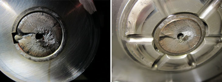
Left: Shaft break on turbine side
Right: Shaft break on pump side
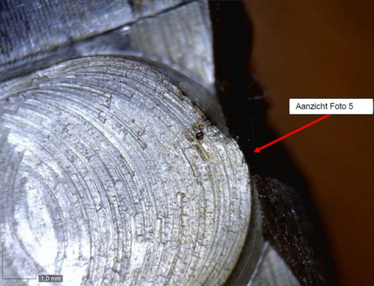
Conclusion of shaft break inspection
The fracture surface, as seen in the above photos, is a typical fatigue fracture. Clearly visible are the growth lines running counterclockwise, and the residual fracture surfaces to the right of the center. From the damage pattern, it is evident that the crack initiation occurred in the transition between the bottom of the keyway and the wall of the keyway.
During the rupture of the shaft, the fracture surface caused some damage to the growth lines. This can be considered as secondary damage. The residual fracture, which is heavily plastically deformed, is also considered secondary damage.
Keyway with a poor surface and transition to the necking of the shaft
The reason the fracture originated specifically here is found in the keyway of the shaft. This keyway has been machined with a dull milling cutter, introducing small cracks during the design process. Additionally, there is a necking of the shaft, precisely located at the keyway. This necking is finished with a too-sharp transition, leading to notching. This is the weakest part of the shaft and should never be present in or near a keyway.
A common cause of fatigue fracture is a misalignment. This alignment error results in a highly varying dynamic load, which, in turn, accelerates the fatigue process.