This article is part of the whitepaper: “monitoring mechanical behaviour of reciprocating machinery”. Request the whitepaper here »
Impact measurements are used as a reliable method to monitor excessive mechanical movements of reciprocating compressors. Previously, vibration measurements were used, but this did not provide accurate measurements to monitor impact. This is because of the significant difference between a vibration signal and an impact signal.
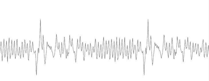
As the piston moves through the cylinder, impacts are caused, which produce high amplitude spikes of a very short duration (figure 1). Traditional vibration measurement sensors are not suitable to monitor these impact signals as impacts barely affect the vibration signal. Impact sensors (or transmitters) are suitable to detect mechanical clearance and looseness on reciprocating compressors at an early stage.
Excessive mechanical clearance can develop quickly, which is why impact measurements are used for monitoring and, if necessary, shutting down the reciprocating compressor. Automatic shutdowns or trip functions are activated based on pre-set alarm values, which are related to the intensity of the impact and the amount of impacts above a defined threshold, within a certain timeframe.
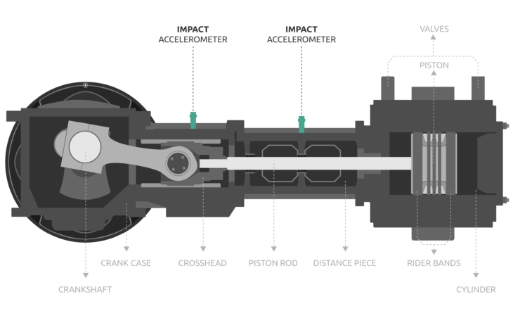
An impact sensor can be placed on the distance piece perpendicular to the direction of movement of the piston rod in the compressor cylinder. An impact sensor can also be placed on the crosshead (figure 2).