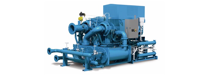
A centrifugal compressor uses centrifugal force to build pressure and is used in various applications. The compressor accelerates air from the center of the impeller wheel and then slows it down in a diffuser. During this air expansion process, the kinetic energy is converted into potential energy in the form of air pressure.
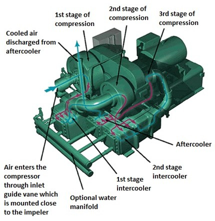
Multistage centrifugal compressors, particularly three-stage ones, are present and necessary in many factories. Each individual stage can create pressure increases from 2:1 to 3:1, and a subsequent third stage can increase this to a pressure increase of 8:1. Another major advantage of three-stage compressors is the simple regulation of temperature and moisture at each compression stage.
A centrifugal compressor is a complex machine and consists of many components:
- Motor
- Main gear to drive air compression phases.
- Inlet throttle valve or inlet guide vanes (IGVs)
- First air compression stage
- Intercooler 1
- Second air compression stage
- Intercooler 2
- Third air compression stage
- Aftercooler
- Blow-off valve
- Check valve
- Control panel
application
Modern centrifugal air compressors are efficient, reliable, and compact and are usually placed on a single foundation including the drive, gearbox, cooling, piping, and control panel. Modern centrifugal air compressors contain advanced technology which brings many benefits to the end users. These include oil-free air supply, simple installation, inexpensive operation, and easy maintenance. As a result, centrifugal compressors are widely used in many industries:
- Oil & gas
- Chemistry
- Petrochemicals
- Energy
- Pulp and paper industry
- Food industry
- Textile industry
Failures and causes
A malfunction or mechanical failure of a centrifugal compressor can have serious consequences for a factory’s production process. It will not only cause other equipment to malfunction but also presents increased safety risks to people and the environment, production downtime, lost production revenues, and expensive repairs.
Failures can have various causes but the most common is mechanical component failure due to imbalance, misalignment, metal fatigue, insufficient or incorrect lubrication, sealing faults, and substance build-up.
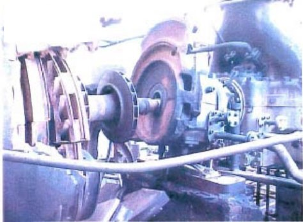
The shaft is the critical rotating part to transfer motion and carry forces within the compression mechanism. The bearings are mounted on the housing to support both the shaft and the shaft itself. Therefore, shaft vibrations or vibrations on the bearing housing are the first symptoms and a reliable indicator of many problems with the centrifugal air compressor system.
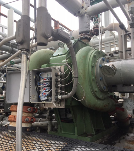
Machine monitoring
For many factories, the reliable operation of centrifugal compressors is crucial. It is therefore important to monitor these machines on various indicators to gain insight into machine condition so that failures can be prevented. Vibration monitoring is one of the most commonly used methods that quickly detect incipient failures before they can cause serious consequences. Implementing vibration monitoring therefore brings many benefits that all together ensure better financial results:
- It increases uptime and production output
- It prevents unexpected downtime and repair work
- It contributes to efficient maintenance planning
The American Petroleum Institute (API) is a major advocate for the development of standards for machine monitoring and the API-670 standard they established is used by many end users of rotating machines. Since 1970, API has accepted proximity sensors as suitable measuring instruments for determining acceptable shaft vibrations during factory acceptance tests (FAT). The API 670 was later supplemented with content about the temperature and material for housing vibration measurements on gearboxes.
In 2001, the API 670 standard was revised again and given the title Machinery Protection Standard. Since then, the API 670 has become the most applied standard for vibration monitoring in the world because it contains recognized “good technical practices” for vibration monitoring systems.
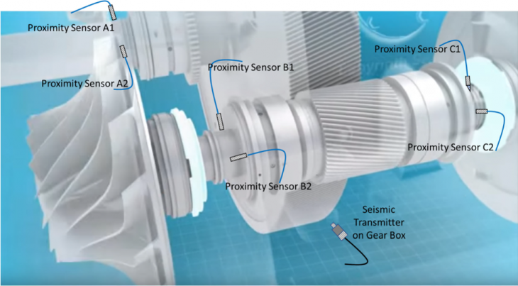
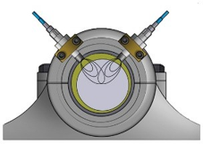
Figure 4 comes from the API standard and shows that at least two axial and two pairs of radial vibration sensors (X and Y) must be placed on a centrifugal compressor with hydrodynamic bearings for properly monitoring shaft vibrations. From experience, we also advise mounting at least one set of seismic vibration sensors on the bearing housing for monitoring housing vibrations.
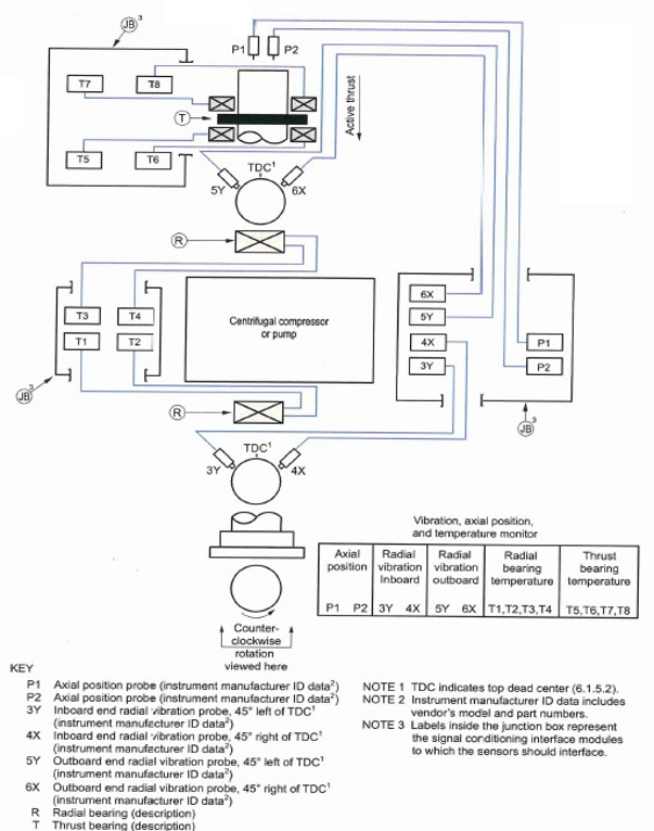
sensors
Istec provides the most accurate and reliable measurement systems and sensors from reputable suppliers and offers all support to maximize the safety and availability of machines.
For monitoring a three-stage centrifugal compressor, it is advisable to mount at least one sensor (Metrix MX2034) per impeller for measuring radial vibration and at least one seismic transducer (ST5484E) for measuring vibrations of the gearbox. The 4-20mA signal can be led to a PLC/DCS and the buffered raw signal can be used for vibration analysis. For obtaining a complete picture, an XY measurement must also be mounted at each bearing, using two sensors.

Advanced features of MX2034 proximity transmitter
Cross talk interference prevention
 The Cross Talk-elimination functionality is used when proximity sensors are mounted close together (25mm or less). This functionality is applied to one of the sensors that may disturb another sensor nearby. By changing the oscillation frequency of the transmitter, it differs from the other sensor thus preventing Cross Talk interference.
Peak suppression
 The peak suppression functionality is applied to prevent high amplitude electrical noise from outside the vibration monitoring system from affecting the operation of the measuring system. Temporary high amplitudes that are of short duration, usually less than 50 milliseconds, are suppressed thus reducing the chance of a false-positive, or an unreliable result.
4‐20mA decay rate
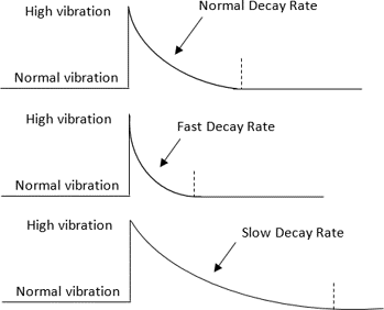 This functionality is used to adjust the current decay rate (decay rate) of the 4-20mA signal. When the sensor detects higher vibrations, it immediately increases the current output to reflect the change in vibration level. However, the current will not immediately drop significantly when the high vibrations stop. The adjustable decay rate ensures consistent measurements of the 4-20 mA output at different machine speeds.
